Explanation of XY- and Z-Tolerance
FDM 3D printing builds a part by depositing individual layers at a specified resolution. These parts are subject to two tolerances (XY- and Z-). The XY-planes are the planes parallel to the build platform. The Z-direction is the direction of the build.
Stratasys FDM prints exhibit an XY-tolerance of +/- 0.005 in. or +/- 0.0015 in./in. The Z-direction has an additional tolerance of (-0.000/+ layer height). The standard Stratasys tolerance range serves well for most applications, but, occasionally, there is a need for a higher degree of accuracy for specific features. This is where part orientation plays a significant role.
Often parts will have features that are perpendicular to one another; this means no matter how a part is oriented, certain features will show higher accuracy than others. It is important to determine the design features that are most critical for the part function, to determine the best build orientation for a 3D printed part.
Bearing/Bushing and Shaft Example
Let’s walk through an example of fitting a basic 3D printing ring to an off-the-shelf metal rod:
- 3D Printed Ring: custom geometry, subject to tolerances of 3D printing
- Off-The-Shelf Metal Rod: predefined geometry, subject to tolerances of extrusion/casting process – typically +/- 0.001 in. or less in diameter
A part is being 3D printed to fit with a shaft. The hole the axle fits into is considered an important design feature for function. The shaft’s ability to rotate depends on the fit between the shaft and the bushing hole. The less accurate the fit is between the bushing hole and shaft, the more it will tend to wobble. Consequently, this could lead to part failure or decreased performance.
Below is a diagram of a simple 3D printed ring, with the intended build layers marked in green:
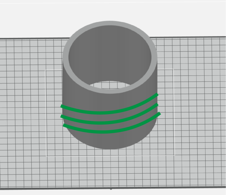
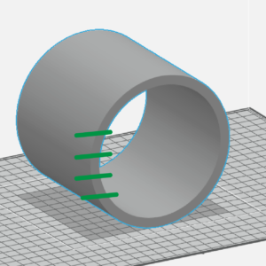
In this example, the vertical build (left, above) will result in the 3D printed part having an improved accuracy of the circular features. The horizontal build (right, above) will cause the circular features to be subject to the Z-tolerance, leading to a less accurate print. The horizontal build would also create a stair-stepping effect in the inner circle.
The stair-stepping effect is relatively common, but easily avoidable in FDM printing. On this feature it would result in the difference between a round ring (left, below) versus a polygon-shaped ring (right, below).
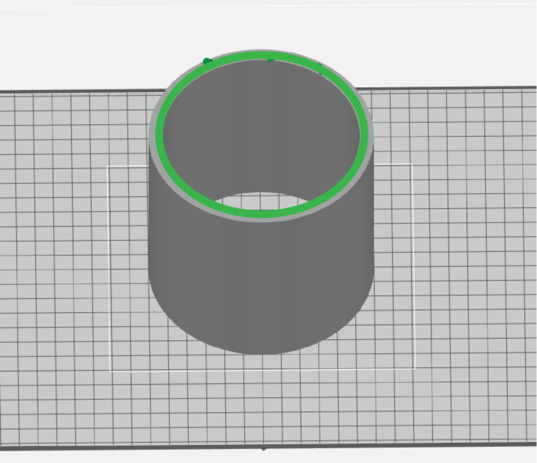
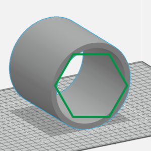
When printing parts, our team at Purple accounts for any potential stair-stepping effects – orientating your part to support the most critical design features.
Summary
The presence of both XY- and Z- tolerances in 3D printing can result in parts that perform differently based on build orientation. When prototyping with 3D printing, it is important to determine the most critical feature for performance and the tolerances for off-the-shelf components early on.
The features that are the most critical to the part function should be oriented with the plane profile parallel to the build tray. Some parts will have critical features perpendicular to one another. In this scenario, the feature that is most important to part function and performance will dictate the build orientation.
Be on the lookout for further blog posts in the future for more complex examples on proper build orientation for FDM printed parts!
If you would like to discuss how print orientation will affect your 3D printed part output, contact our team at 949.474.9222 or [email protected].

Meet Alex Goldsberry
As a Sales Engineer for Purple Porcupine, Alex focuses on bringing value to customers through his knowledge of additive manufacturing, engineering, and 3D printing technology. Out of the office, Alex enjoys reading investment articles and analyzing stock trends. If you haven’t had a chance to meet Alex yet, stop by our office and say hi, or connect with him on LinkedIn!
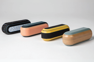
Why FDM And PolyJet Are Essential Technologies
I have been in the 3D printing industry since 2013. I’ve seen how trends come and go, new technologies promise to be a silver bullet, and how everyone is holding
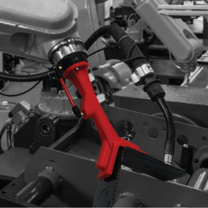
End of Arm Tooling with FDM
Robotic devices are typically used as a cost-effective alternative to repetitive and labor-intensive operations when manufacturing, inspecting, packaging, and transporting products. In most cases, robots use end of arm tool
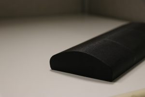
30 on 3D: The Benefits of Adding Clear-Coat to FDM Parts
When creating a prototype that requires a precise look and feel, adding something as simple as an acrylic clear-coat goes a long way. For this edition of 30 on 3D,
